


ELECTRONICS and ELECTRICAL
Electronics and Electrical FAQs::
In recent years LEDs and LED lighting has emerged as the leading candidates for next-generation lighting due to their low energy consumption, high efficiency, and long life.
The following are few topics and keywords covering the comparatively complex field of LEDs.
POWER SUPPLIES
Topic 1: Switching power supplies
POWER SUPPLIES ARE USED IN VIRTUALLY ALL ELECTRONIC DEVICES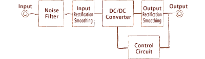
A switching power supply outputs a stable DC voltage based on rectification and control via a semiconductor switch that performs ON/OFF operation at high frequency. It is the preferred choice in a variety of devices due to its relatively small size, light weight, and high efficiency. Additional features are often included, such as noise filters, activation/rectifier circuits, and protection functions for better performance.
Topic 2: AC/DC and DC/DC converters
ESSENTIAL FOR VOLTAGE RECTIFICATION
• An AC/DC converter is a switching power supply that converts AC voltage to DC.
• A DC/DC converter is a switching regulator that converts one DC voltage (i.e. from a battery) to another. Normally features excellent switching efficiency.
Topic 3: Fixed voltage drive
SIMPLE, COST-EFFECTIVE LED LIGHTING METHOD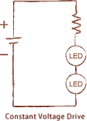
This type of driving method provides the required current by supplying constant voltage to the LED(s). This is the simplest method to implement and is cost-effective. However, one major drawback is that the current will vary based on the different Vf of each LED and the heat generated by the chip itself. This will result in fluctuating brightness. Heat loss at the limiting resistor must also be considered.
Topic 4: Fixed current drive
EFFICIENT LIGHTING METHOD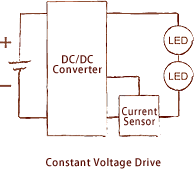
This type of drive provides constant current, improving efficiency while reducing heat generation. Although more complex and costly than constant voltage circuits, brightness fluctuations are minimized.
Topic 5: Duty control method
REQUIRED FOR ADJUSTING THE BRIGHTNESS WITHOUT CHANGING THE COLOR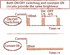
This method controls the brightness by switching the LEDs ON and OFF at high speeds with constant forward current. The duty ratio is expressed as the fraction of the ON/OFF cycle the LED is lit up (or ON).
Brightness is determined based on the value of the forward current (If). This type of circuit is used in circuits where the brightness fluctuates greatly with just a small change in current or applications where the color tone varies with brightness.
Topic 6: PWM control
BRIGHTNESS BASED ON DUTY FACTOR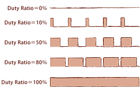
The PWM (Pulse Width Modulation) method controls LED brightness by varying the pulse width. The ratio the LED is ON is called the duty cycle. LEDs are turned ON and OFF at high speed and the brightness is adjusted by varying the ON time. If switching is early, residual imaging may occur.
Topic 7: Phase control
BRIGHTNESS CHANGES BASED ON THE AMOUNT OF POWER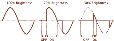
Phase control involves controlling the power supplied to the load using power control elements such as thyristors. Current flows only when a signal is supplied to the Gate terminal of the thyristor, even if voltage is provided. Current (and therefore brightness) is adjusted by controlling the conduction time.
Advantages include continuous adjustment due to the wide output range, a small, low-cost control circuit, and reduced power loss.
Topic 8: Wireless communication
SIGNAL TRANSMISSION VIA ELECTROMAGNETIC WAVES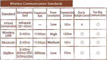
This method transmits information without wires. Various standards are used, such as infrared, Bluetooth, Zigbee, wireless LAN, and radio broadcast. Differentiating factors include transmission rate, communication distance, and power consumption.
Topic 9: Volt, Watt, Amps and C
A: That's not a question, but okay. Volts are electrical potential, amps are electrical current, watts are total power equal to volts*amps, and C is electrical current as a function of battery capacity. Think of volts as the width of a pipe: In general, a wider pipe has more punch than a narrower one. Think of amps as the water flowing through a pipe: Some pipes can only handle little trickles of water, and others can handle lots of water pushing through with great force. Think of watts as a combination of volts (pipe width) and amps (flow of water): A large pipe with water flowing through really slowly has the same output as a small pipe with water blasting through it. This is why high-voltage applications are preferred over high-current applications, as a stream of water zooming at 200mph through a 1"-diameter pipe is much more dangerous and difficult to maintain than a calm, 3mph flow of water through a 4'-diameter pipe. As for C rates, that's just a function of current draw and battery capacity. Any power source discharged at a 1C rate will be depleted in 1 hour, any power source discharged at a .25C (or C/4) rate will be depleted in 4 hours, and so on. As an example, a 1.8Ah AA NiMH capable of an excellent 10C discharge rate can manage 1.8*10=18 amps.
Topic 10: Parallel or Series
Series connections have a device's positive terminal connected to the next device's negative terminal. This is what you get when you line up some ordinary C-cell alkalines (for example) end-to-end, like in a Maglite or other flashlight. This arrangment adds up the voltages of the cells. Such a battery neither handles more current nor contains more mAh capacity than a single cell. This is the opposite of a parallel configuration, which has positive terminals joining together and negative terminals joining together. An example is those 3AA>1D adapters where all three AA cells' positive terminals meet at the top, and all their negative terminals meet at the bottom. Such a configuration has the same voltage as a single cell, but can handle more current draw (or contains more capacity). For example, 1AA alk can push about 500mA at around 1.5V for about four hours. 2AA alks in series can push 500mA at around 3V for about four hours. 2AA alks in parallel can push 1000mA at around 1.5V for about four hours (or 500mA for eight hours, and so on).
Topic 11: Direct Drive and Regulated
A direct drive (DD) light is one that has the battery directly connected to the bulb or LED. A regulated light has some sort of driver circuitry between the two. A DD setup is heavily affected by the battery size and type. In a regulated light, the circuitry will try to minimize the effects of the battery. The huge majority of incandescent lights are DD. They start out bright, then fade over time. The effect is greatest with alkalines, which don't do well in many situations. The effect is least noticable with Lithium-Ions, which maintain a steady voltage under relatively heavy loads. This is why traditional Maglites, which are DD by alkalines, start out bright for about half an hour, then quickly fade out and become dim for the next few hours until the battery gives up. One example of a regulated incan, which provides rock-steady output for the majority of the battery life, is Surefire's A2. In order to drive mostly similar LEDs with wildly different battery solutions, a regulation circuit allows steady output for as long as the battery has power. As an example, the Fenix E0 runs on a single AAA alkaline for eight hours with no decrease in output. If it were DD, it wouldn't light up at all, much less provide constant output. An appropriately DD LED flashlight would be one driven by button or coin cells at somewhere above the LED's Vf. This results in a long runtime with slowly decreasing output, determined by the battery's remaining power.
Topic 12: Boost and Buck
Boost and buck circuits increase and decrease, respectively, the output voltage of a battery. This is used because of Vf requirements (discussed elsewhere in the Welcome Mat). Such a circuit will usually have battery + and - inputs as well as LED + and - outputs. The interesting thing about these circuits is that they can also be used to tweak battery current consumption, as a boost circuit will draw more current from the battery than is flowing at the output, and a buck circuit will draw less current from the battery than is flowing at the output. This generally means that boost circuits are hard on cells, while buck circuits are easier on them.
For example, 2AA NiMH powering an XR-E with a Vf of 3.7V at 700mA would require a boost circuit. If the circuit was 100% efficient (not actually achievable), the following equation would apply:
3.7V/2.4V*700mA= ~1080mA
This means that we can use a lower voltage source like 2.4V, but we will have to draw over 1A to produce the desired 700mA at the emitter.
For real-life circuits with efficiencies under 100%, simply divide the required battery current by the efficiency (expressed as a number between 0 and 1). For example, an 85% efficient boost circuit applied to the above situation would result in the following equation:
1080mA/0.9= ~1270mA
For buck circuits, the opposite situation applies. For example, powering a 5mm LED with a Vf of 3.4V at 20mA with a 90% efficient buck circuit on a 9V battery would result in the following equation:
3.4V/9V*20mA/.9= ~8.4mA
Keep in mind that these are simplified situations, with real flashlights being influenced by a number of limiting factors.